
GN9120 DECT Wireless Headset
Interface
for Amateur Radio with PTT
Interface
for Amateur Radio with PTT
Background
Gerald, VK3GJM devised a simple way of interfacing a GN9120 DECT wireless headset to amateur radio equipment. His full article is described here.
The GN9120 is an excellent bluetooth type headset, with superb audio quality and a clear signal range of 100 metres or more. Because it a DECT unit instead of Bluetooth, there is no manual pairing required. It operates more like a digital cordless phone instead. The headset will provide an 8 hour talk time and 24 hour standby time.
After deciding that it would be a great addition to the shack, particularly for working crossband, I obtained an identical headset on eBay for a very reasonable price .
I reviewed and took note of Gerald's modifications, but wanted to try and keep the circuit as original as possible so that I could have the option of also using the GN9120 to interface to telephones as it was originally designed to do. In view of those requirements, I decided to re-invent the wheel and came up with this version of the modification.
Modifications
Monday, 4th July, 2010 10:44

Converting the GN9120 for Ham Radio Use
This modification only requires the addition of one component and two connector sockets to the original GN9120 for it to operate with almost any amateur radio transceiver.
I chose to try and retain the internal isolation transformers, hoping that they would provide additional isolation against ground loops and for electrical isolation between the headset base unit and the radio.
I also listened to Gerald using his headset on the local 2m and 70cm frequencies and noted that he was using VOX on his IC910 to activate his PTT. Since my radio's don't have a VOX, I decided to investigate what would be required to provide a bluetooth activated PTT capability.
Gerald advised that he had completely buzzed out the SMD IC's in the base unit and was not able to find any line that would facilitate a PTT capability.
This made me realise that we would need to take advantage of the existing logic available to us and use something like a PIC to provide the additional required logical functionality.
By Ben Crnojacki VK3KBC
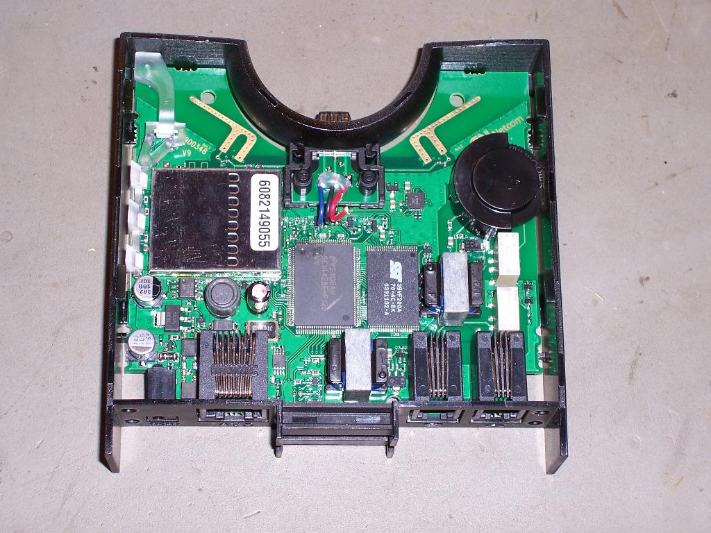
Picture 1, GN9120 PCB with Plastic Casing Removed
Picture 10, Flowchart of the PIC12F683 PTT Routine
This modification is offered as a all care, no responsibility mod. People wishing to modify their GN9120 or radio do so at their own risk.
This modification is not complex, however it does require a certain level of technical competence. If you are not experienced in repairing or servicing complex radio equipment, then you will need to enlist the assistance of someone who is, in order to perform this upgrade.
The GN9120 uses extremely small surface mounted components, some of which will be prone to damage in high static fields. It is important to follow safe ESD practices and ensure that you are working in a fully static safe environment. It is also difficult to access some of the solder points and unless you are confident in your soldering ability, I would recommend that you do not attempt this on your own.
Whilst I have performed these modifications successfully without incident, I cannot be held responsible if you choose to go ahead with the modification and it does not work out for you, or you damage your radio in the process. This information is provided as-is. If you choose to use this information, then the risk is entirely yours.
Good luck, hope to hear you on the air soon.
73s and regards
Ben
VK3KBC
Disclaimer
Interface Parts List
The following parts are required for the basic interface modification (without the bluetooth PTT):
The following parts are required for the basic interface modification (without the bluetooth PTT):
| Qty | Part |
| 1 | 3.5mm panel mount socket |
| 1 | 2.5mm panel mount socket |
| 1 | Radio Mic plug to suit transceiver |
| 1 | 3.5mm inline plug to suit transceiver audio out |
| 1 | 47K 1/8W or 1/4W resistor |
| 2 | Lengths of shielded single core cables |
Bluetooth PTT Upgrade Parts List
The following additional parts are required for the bluetooth PTT modification:
The following additional parts are required for the bluetooth PTT modification:
| Qty | Part |
| 1 | PIC12F683P |
| 3 | Optocouplers (Possibly 4N35) I used generics |
| 1 | 78L05 Regulator |
| 1 | 1uF 16V Tantalum |
| 1 | 0.1uF monolythic capacitor |
| 3 | 10K 1/8W resistor or flatpack strip |
| 3 | 100R 1/8W resistor *(may need adjustment) |
| 1 | 220R 1/8W resistor |
| 1 | 5mm Blue LED |
| 1 | 1K 1/8W resistor |
| 1 | BC548 transistor |
| 1 | Veroboard |
| 1 | Length of flat multicolour ribbon cable |
| 1 | Length of shielded single core cables |
The first modification consists of mounting the 3.5mm and 2.5mm sockets onto the case as shown in the following photos and wiring them to the respective audio transfomer outputs.
The audio out transformer is connected to the 3.5mm socket tip terminal via a series 47k resistor to lower the level into the transceiver's microphone input..
The stereo 3.5mm socket ring terminal is reserved for PTT out if you choose to complete the PTT modifications also.
The mono 2.5mm socket is used for the transceiver's speaker out line or headphones output.
Completing these modifications will allow you to use the GN9120 by manually activating the transceiver's PTT using a seperate switch or MOX button, or by using it with a transceiver fitted with VOX.
This configuration worked really well for crossband QSO's where I plugged the 3.5mm line into the microphone input of my 2m transceiver, locked the PTT with the MOX switch and plugged the 2.5mm line into the speaker out of my 70cm radio.
The use of the unit's two existing isolation transformers worked out extremely well and 'on air' audio reports confirmed that this configuration provides an excellent audio response when interfaced with amateur transceivers.
Originally I had tried a wiring configuration where the two transformers had a common earth, but this configuration was inferior as it had resulted in noticeable earth loops when using one transceiver for transmit and a different one for recieve.
By retaining the transformers and keeping the Bluetooth Base Unit and transceiver's ground connections all separate, the is no chance of ground loops or hum being induced and transmission quality is excellent.
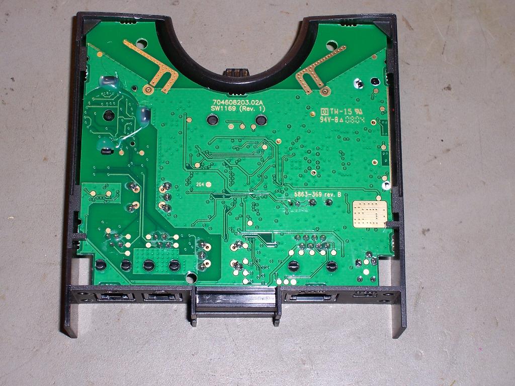
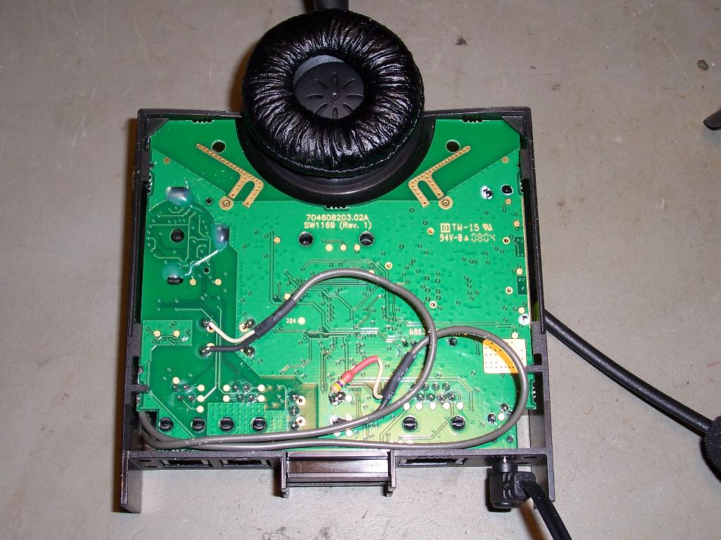
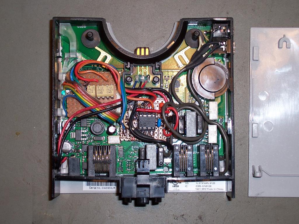
Picture 2, Rear of GN9120 PCB with Plastic Casing Removed
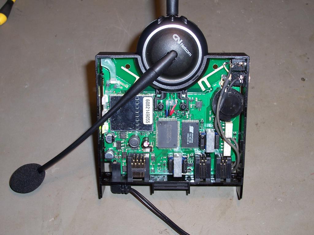
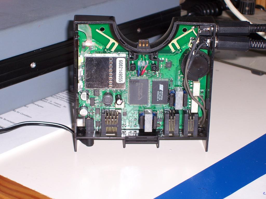
Picture 3, GN9120 PCB with additional 3.5mm and 2.5mm sockets at top right of photo
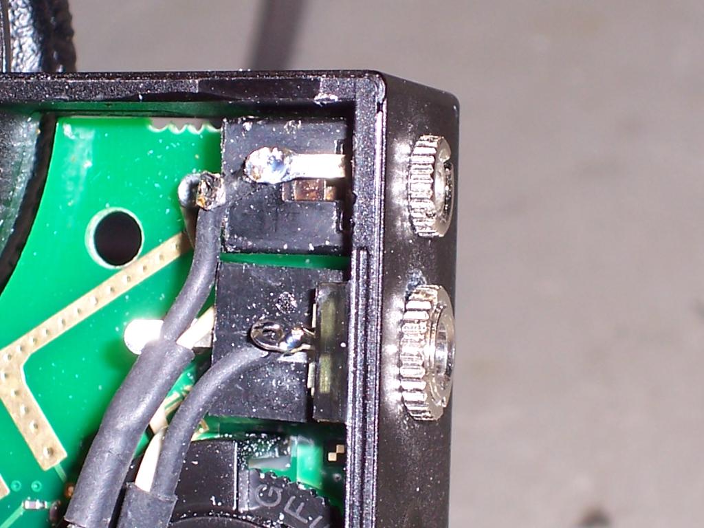
Picture 4, GN9120 showing additional 3.5mm and 2.5mm sockets
From Transceiver Speaker Output
ToTransceiver Microphone and PTT
Picture 5, GN9120 showing transformer termination points and TX level resistor
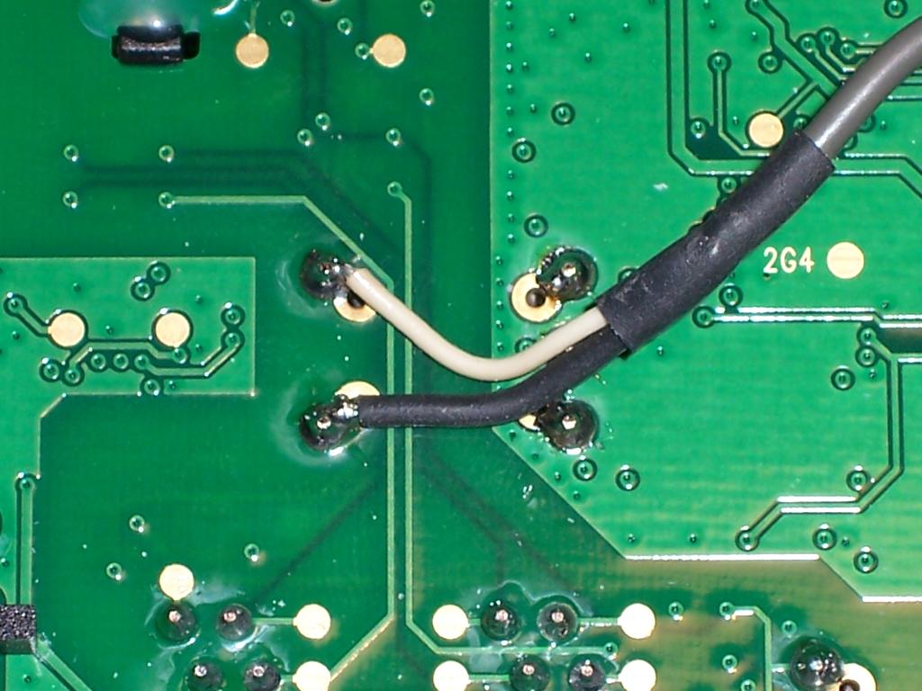
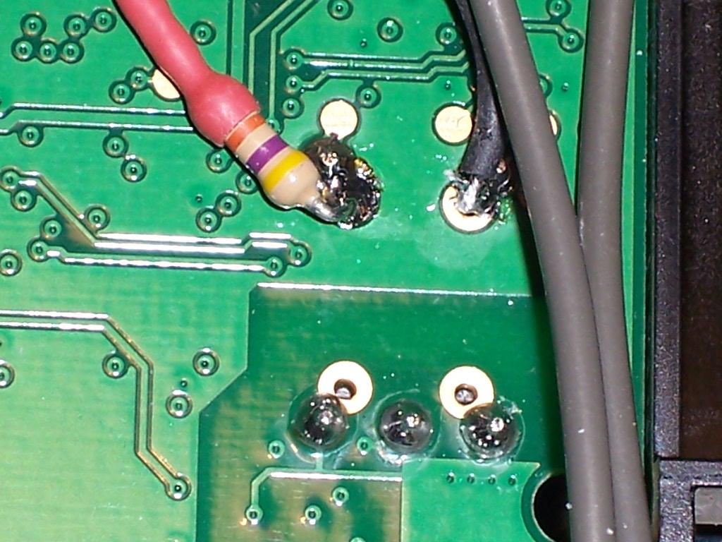
Pictures 6 & 7, showing transformer termination points and TX level resistor
Picture 8, showing working interface without Bluetooth PTT function
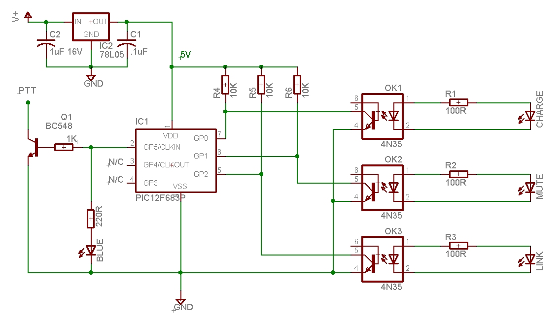
Note that the optocouplers load the Charge, Mute and Link LED's a little. Gerald's transistor interface (shown below) is the prefered interface method as it does not load the LED's.
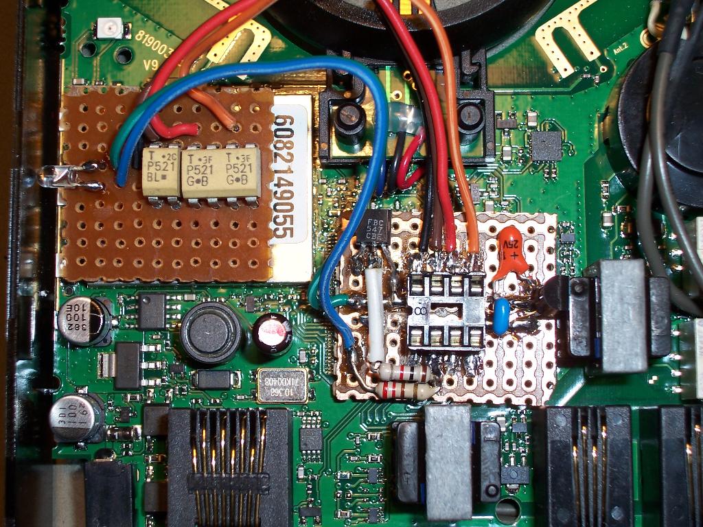
Picture 11, showing Optocoupler board (left) and PIC board (right)
Gerald has now modified his GN9120 to incorporate the PTT modification also. He has used surface mounted components to minituarise the PTT board and this has resulted in a much neater implementation.
Keep in mind that if you're contemplating Gerald's PTT layout, he has also removed the isolation transformers, which gives him a little more room above the LSI Chips than when the transformers are retained.
In place of the optocouplers, Gerald has used PDTC114EU NPN Digital Transistors. These have inbuilt bias and emitter resistors and are ideal for this application.
The inputs of the transistors are terminated on the smd LED current limiting resistors just at the edge of the metal bluetooth module. A multimeter probe on these resistors will show 0V when the LED's are inactive and just over 2 Volts when they are active.
Gerald used a conventional EPROM / PIC programmer to program his PIC using the inverting hex file above.
The board is attached by double sided tape to the LSI chips below. (Make sure you use a static strap and ESD safe environment to discharge any charge built up on the tape before adhering it to the IC's).

Picture 12, showing Optocoupler connections to the Charge, Mute and Link LED's
Picture 14, Gerald's (VK3GJM) PTT board showing final layout prior to reassembly
Figure 2, Source Code written in Mikroelektronika PIC-BASIC (only for use with non-inverting LED interface (not compatible with Optocoupler interface unless non-inverting design is used)
Figure 1, Source Code for Inverting Version (using OptoCouplers)
written in Mikroelektronika PIC-BASIC
written in Mikroelektronika PIC-BASIC
:020000000328D3
:1000060007308312990083169F011F3085008312E3
:100016000514051585148512051D12280E280518C8
:1000260015280E288518182819280E280230FB00D6
:100036000430FC00BA30FD00FD0B1F28FC0B1F2806
:10004600FB0B1F280000851C29283028051D2C289D
:100056000E2805182F280E281928851685183528E4
:1000660085121928051D38280E2805183B280E2844
:0400760030283C28CA
:02400E00F20FAF
:00000001FF
:020000000328D3
:1000060007308312990083169F011F3085008312E3
:100016000510051185108512051912280E28051CD4
:1000260015280E28851C182819280E280230FB00D2
:100036000430FC00BA30FD00FD0B1F28FC0B1F2806
:10004600FB0B1F28000085182928302805192C28A5
:100056000E28051C2F280E2819288516851C3528DC
:1000660085121928051938280E28051C3B280E2844
:0400760030283C28CA
:02400E00F20FAF
:00000001FF
Inverting Hex Code Non-Inverting Hex Code
Figure 3, 12F683 Hex Code for Inverting and Non Inverting LED interfacing.
The headset itself operates in a number of modes and the full details can be found in the User Manual which can be downloaded from the Internet.
For amateur radio use, it can be used in the following two modes:
MODE 1 (NO PTT MODIFICATION):
When the headset is taken off the cradle, the link is automatically engaged and the Link LED is illuminated.
The unit will now respond to headset microphone audio by flashing a 'Talk' LED and TX Audio is sent to the transceiver via the 3.5mm socket. Any audio presented to the 2.5mm socket will be heard in the headset earpiece. There is NO PTT sent to the transceiver.
If you activate the transceiver MOX button and thereby engage the PTT on the transceiver, microphone audio will be active and you can operate the transceiver with locked PTT. If the RX audio comes from another transceiver, then you can work crossband in this mode. You can also use VOX instead of MOX for half duplex communications.
Activating the MUTE button on the headset (requires two presses of the ' - ' button in quick succession) will disable the TX audio. This is handy when operating VOX and in a noisy environment.
When in MUTE mode, a beep is heard every 15 seconds or so in the headset earpiece.
If the headset unit is out of range of the base, twin beeps in quick succession will be heard in teh earpiece and the RX audio will dissappear. Moving back in range will restore operation.
Pressing the Multifunction (MFB) button on the headset will disable the link. If MOX was used to activate PTT, then this will result in a residual carrier until the MOX is disengaged.
MODE 2: (PTT MODIFICATION)
When the headset is taken out of the cradle, the link is automatically engaged and the Link LED is illuminated.
The unit will now respond to headset microphone audio by flashing a 'Talk' LED and TX Audio is sent to the transceiver via the 3.5mm socket. Any audio presented to the 2.5mm socket will be heard in the headset earpiece. There is no PTT sent to the transceiver at this time.
You can consider that the headset is in RX Only mode only at this time.
When the MUTE function is activated by pressing the ' - ' button twice in quick succession, the unit now remains in RX but is also in MUTE mode. I call this RX Mute mode. The headset delivers the RX audio as well as a short 'pip' tone every 15 seconds or so.
The tone is not disconcerting and is similar to the pip heard when an audio conversation is being recorded on commercial systems.
Pressing the - button twice in quick succession will disable the MUTE and activate the PTT mode. The unit will now transmit the audio from the headset and receive any audio being presented to the 2.5mm socket. The RED Mute LED will now change to BLUE, indicating TX.
Pressing the ' - ' button twice in quick succession will toggle the unit back into MUTE mode and deactivate the PTT mode, placing the transciever into RX mode. The Mute LED will now change back to RED again, indicating RX.
Pressing the - button twice in quick succession again will disable the MUTE and activate the PTT mode. The unit will now transmit the audio from the headset and receive any audio being presented to the 2.5mm socket. The RED Mute LED will now change to BLUE, indicating TX and so on.
Each time that the ' - ' button is pressed twice quickly, the headset will toggle between RX Mute and TX mode or TX and RX Mute mode.
If at any time the headset MFB is pressed, the Bluetooth Link will be reset and the radio will stop PTT and revert to RX Only mode.
If the Link is lost due the the headset being out of range, the headset will beep twice every few seconds or so indicating an out-of-range condition. All RX audio and TX audio is disabled but PTT will still be active. Moving back in range restores operation in whatever mode was last used.
If the Link is lost for a few minutes, the PIC12F683 micro in the base unit will detect the Bluetooth Link LED deactivating and will disable PTT and revert the transceiver to RX Only mode. Once in RX Only mode, it will not go back into TX mode without the mute function being activated manually as before.
If the headset is placed on the cradle, the micro will again deactivate the PTT and place the unit in Charge Mode. If the headset MFB button is presset, then unit will activate the Link however if Mute is activated whilst in the cradle, only the RX Only mode will be available. The 12F683 will prevent the PTT from activating if the headset is in the cradle regardless of what other button combinations are activated.
Essentially, the headset must be out of the cradle AND have an active link to the base unit AND be in RX Mute mode for the 12F683 micro to respond to PTT activation commands.
Operation
Note: The above hex code needs to be cut and pasted into a notepad file. Call the file anything with a .hex suffix. For example: "9120.hex" When programming, read the file in Intel Hex format and make sure that the PIC12f683 Clock Source option is set to "Internal with GPIO.4 and GPIO.5 set to I/O".
Alternate Construction
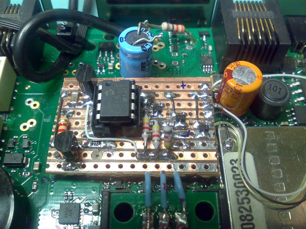
Picture 13, showing final layout prior to reassembly
Picture 9, showing schematic of the Bluetooth PTT function
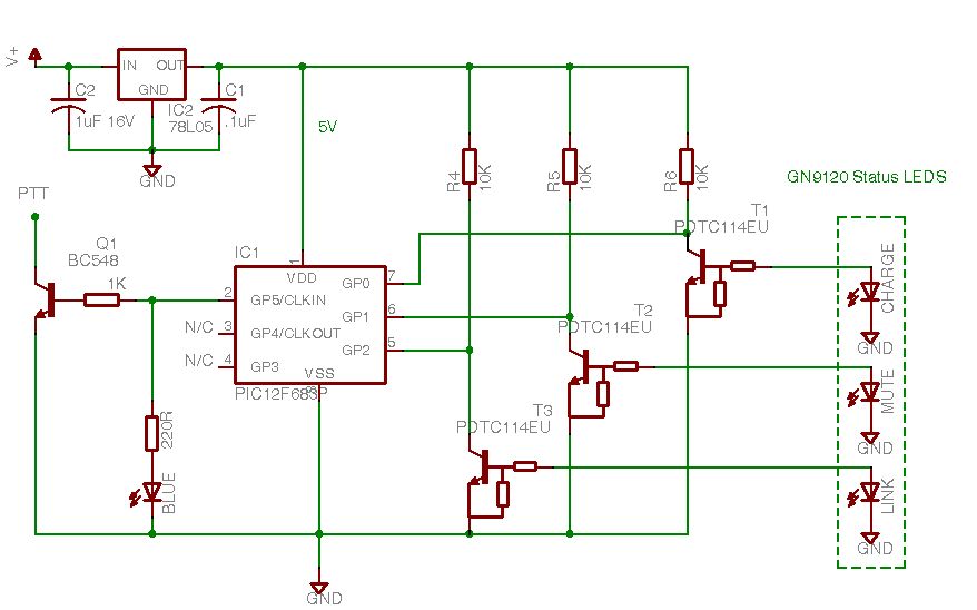
Picture 15, Udated schematic using PDTC114EU's as interfaces instead of the optocouplers.
The above schematic is the prefered interface solution. The original optcoupler interface tends to load the LED's down somewhat which reduces the LED's intenstity a little, whereas this interface doesn't.
There is no reason why the PDTC114EU's can't be replaced with generic NPN transistors and 10k resistors, however additional space on the interface board will be required to accommodate.
There is no reason why the PDTC114EU's can't be replaced with generic NPN transistors and 10k resistors, however additional space on the interface board will be required to accommodate.

Search
