
Background
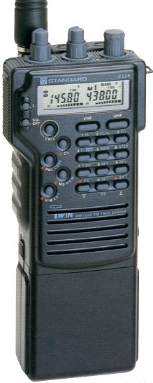
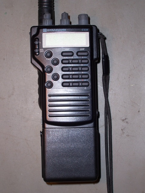
The Standard C-528 Transceiver was released in Australia in the mid 1980's and was a very innovative and popular twin band 2m and 70cm hand-held transceiver and many were sold in VK. At one time it seemed like every VK you spoke to had one.
The C-520 and C-528 were also widely released in Europe and Japan, however I don't believe that they were very prevalent in the U.S.
The C-528 appears identical to the Standard C-520 and I'm not sure what the exact differences are between them, if any.
Electrolytic Problem
A Silicon Chip ESR Meter MK-II Kit was purchased from Altronics and assembled.
A following ESR test revealed that the capacitor which had earlier measured OK for capacitance had an ESR of over 100 ohms (which was the upper limit of the ESR Meter), so it was effectively a high impedance or 'open circuit'.
Since the ESR Meter is capable of performing in-circuit measurements, all miniature electrolytics were subsequently measured in-circuit and were found to be open circuit also.
The capacitors were then removed one by one and of the 13 miniature electrolytics removed, 3 were found to be leaking electrolyte. The electrolyte had actually begun to etch away at the tracks beneath one capacitor and was damaging the silk screen coating on others.
All capacitors were subsequently replaced with tatalum equivalents which were also checked on the ESR meter prior to being installed
Repair
The replacement of the miniature electrolytic capacitors in the Standard C-528 Transceiver involves the following steps:
The replacement of the miniature electrolytic capacitors in the Standard C-528 Transceiver involves the following steps:
Disclaimer
The repair described in this article is not complex, however it does require a certain level of technical competence. If you are not experienced in repairing or servicing complex radio equipment, then you will need to enlist the assistance of someone who is, in order to perform this upgrade.
Since the radio will be disassembled, it is important to follow safe ESD practices and ensure that you are working in a fully static safe environment. There are CMOS semiconductors in the Logic board and on other boards in close proximity, so they will be prone to damage in high static fields.
All replacement capacitors MUST be installed according to the correct polarity! Take note of where the +ve's are on the original electrolytics.
Whilst these modifications have been performed successfully without incident, I cannot be held responsible if you choose to go ahead with the modification and it does not work out for you, or you damage your radio in the process. This information is provided as-is. If you choose to use this information, then the risk is entirely yours.
Miniature Electrolytic Capacitors Removal Process
Whilst most capacitors were reasonably accessible, a number were close to plastic panels or other components which prevented me from using my Weller Soldering Station for the repair. As the repair progressed, I realised that the Weller wouldn't have had the temperature range needed to remove capacitors that were connected to a ground plane, as the heat was being drawn into the groundplane preventing removal of the capacitor ground lead.
For proper removal, a temperature controlled iron was required with a tip diameter of 1.5mm and a length of 15mm. I found that setting the temperature to 425 degrees Celsius was perfect for removing the both capacitor leads, regardless of whether they were soldered to a groundplane.
Completion
When all of the capacitors have been carefully replaced and the radio re-assembled, a test should confirm that the radio is working properly again. There are no adjustments required as a result of the capacitor upgrades.
Whilst a number of local VK's were not experiencing any problems with their radios prior to replacing the capacitors, one faulty radio immediately became fully operational upon re-assembly; no longer experiencing any intermittent transmit problems or noise.
The whole modification cost me approximately AU$5 in parts; a worthwhile investment to extend the life of an excellent radio.
Wednesday, 30 July 2008 20:32
Recent Problems
These radios generally have a history of being solid and reliable performers and reports of problematic behaviour in the past have been rare.
Recently, however, problems have started to appear with varying symptoms ranging from intermittent noises on TX, to radios exhibiting erratic behaviour.
A fellow VK amateur who was experience TX noises on his transmissions recently decided to investigate but was having difficulty in diagnosing the problem, with no obvious issues being found upon preliminary examination.
After discussing the problem on a local 2m Net, another VK mentioned that he found a leaking capacitor in his C-528 and suggested that we should all check the electrolytics in our radios.
The faulty radio was examined for obvious electrolytic leaks and a sample electrolytic capacitor was removed and measured, however its capacitance value seemed OK and didn't appear to be the cause of the problem.
During subsequent discussions on the 2m Net, it was suggested that all electrolytics be double-checked with an Equivalent Series Resistance (ESR) Meter to determine whether the capacitors may be faulty even though they were still reading their correct capacitance values.
This turned out to be an interesting test.
Surprisingly, even some new 'old stock' unused tantalum capacitors were out of specification according to the ESR meter and needed replacing with new devices. The lesson learned is to check ALL replacement caps before installing them into the radio for correct ESR.
When all of the original miniature eletrolytics were replaced by the tantalums, all transmission problems disappeared and the radio functioned like new again.
This finding was passed onto other C-528 owners on the 2m Net and it was later found that all radios checked with ESR Meters had electrolytics which were open circuit.
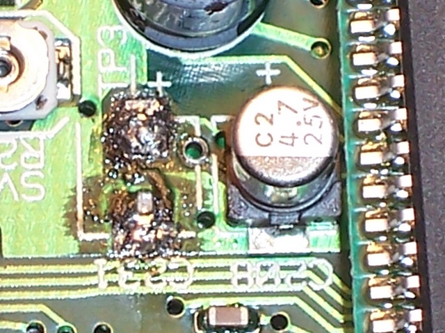
The leaking capacitors had caused damage ranging from discoloured silk screening on the PCB's to actual copper tracks being dissolved or corroded beneath the capacitors.
It was estimated by some owners that if the electrolytics had not been removed when they were, their radios would have been severely corrosion damaged within 12 to 24 months
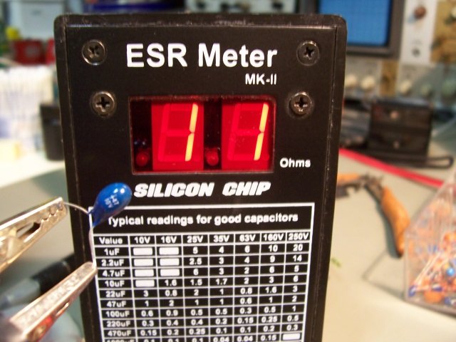
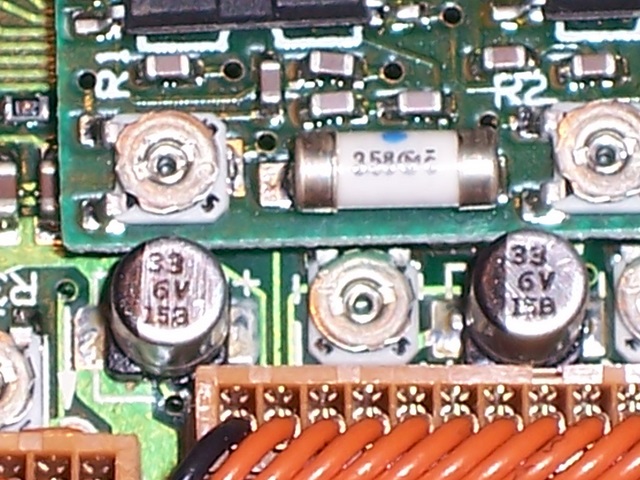
Faulty 'new' tantalum showing 11 ohm ESR
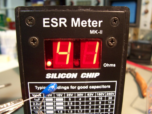
Good 'new' tantalum showing 0.41 ohm ESR
•
Disassembling the radio
•
Desoldering all miniature electrolytics on the top RX / CPU board
•
Removing all electrolytic residue and cleaning the PCB with isopropanol
•
Replacing the miniature electrolytics with equivalent tantalum capacitors
•
Removing the RX / CPU board from the chassis to expose the TX / RF amplifier board
•
Removing the metal shield covering the TX / RF Amplifier board
•
Removing a miniature electrolytic from the TX / RF amplifier board
•
Removing the electrolytic residue and cleaning the PCB with isopropyl alcohol
•
Re-assembling the radio
•
Standard C-528 Service Manual (not absolutely necessary)
•
Equivalent Series Resistance (ESR) Meter. Silicon Chip ESR Meter MK-II Kit (still available from Altronics) or equivalent
•
Very fine-tipped soldering station ( < 1.5mm diameter and > 15mm long ) with variable temperature to 425 deg Celcius
•
Thin solder
•
Good quality solderwick
•
Replacement tantalum capacitors (conventional or Surface Mount)
•
Isopropyl Alcohol (Bulk amounts of Isopropanol are available from Altronics at cheaper rates that buying 100ml from Electronics suppliers - shop around
•
Cotton Buds
•
Electrical tape
•
Zinc Oxide Heatsink Compound
You will need the following:
Electrolytic Capacitor Removal
Remove Front Panel
Consult the Service Manual for disassembly information.
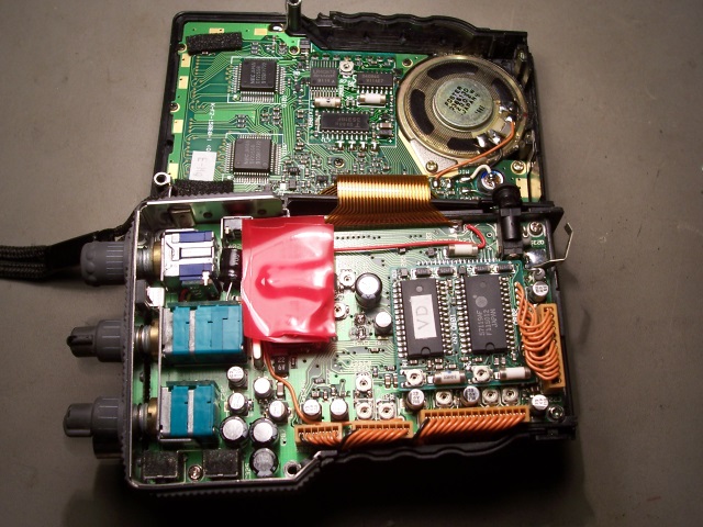
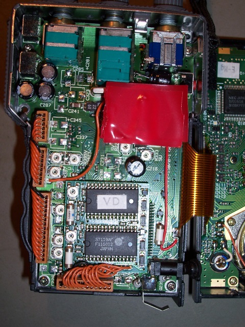
It's a simple process to remove the front panel. You will need to remove the screws at the rear of the radio casing and the ones located beneath the radio that hold the battery spring plate in place. The unit will then split apart exposing the main board housing 12 of the 13 capacitors that need to be replaced.
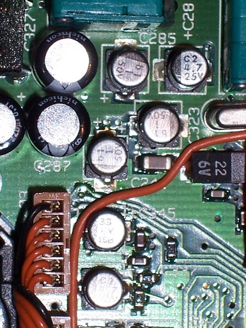
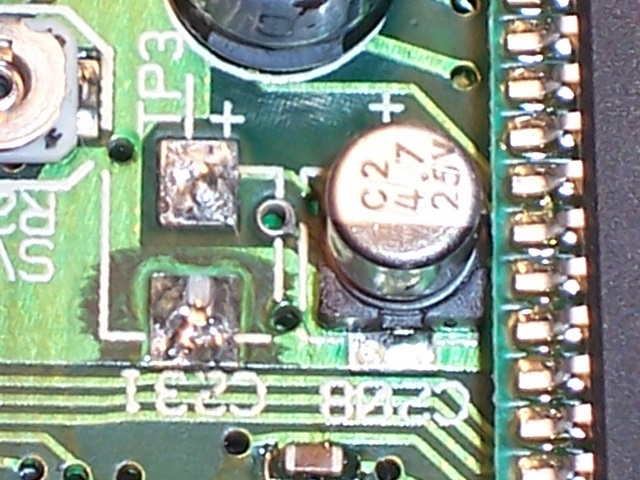
The first thing to do at this point in time is to cover the backup battery with some electrical tape to prevent accidental shorts. I happened to have red tape handy.
The main electrolytics actually showed an ESR that was within specification, so only the miniature caps required replacing.
Consult the Service Manual for disassembly information.
It's a simple process to remove the front panel. You will need to remove the screws at the rear of the radio casing and the ones located beneath the radio that hold the battery spring plate in place. The unit will then split apart exposing the main board housing 12 of the 13 capacitors that need to be replaced.
The first thing to do at this point in time is to cover the backup battery with some electrical tape to prevent accidental shorts. I happened to have red tape handy.
The main electrolytics actually showed an ESR that was within specification, so only the miniature caps required replacing.
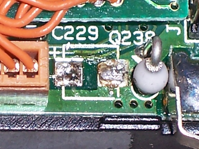
Once the capacitors had all been removed, any electrolyte was removed with cotton buds soaked in Isopropyl Alcohol. More extensively damaged pads were coated with SMD flux before being tinned with new solder.
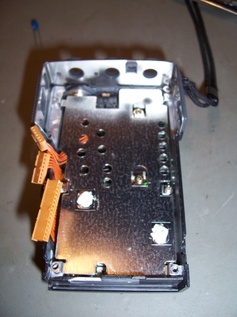
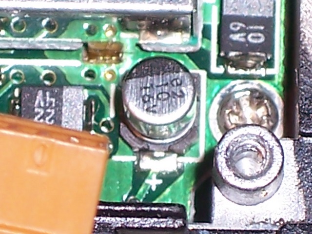
When all of the capacitors were removed from the main board, it too was removed from the chassis, followed by the metal shield. This exposed the RF board, which contained a single miniature Electrolytic capacitor also needing replacement. The photo below shows a replacement blue tantalum in its place.
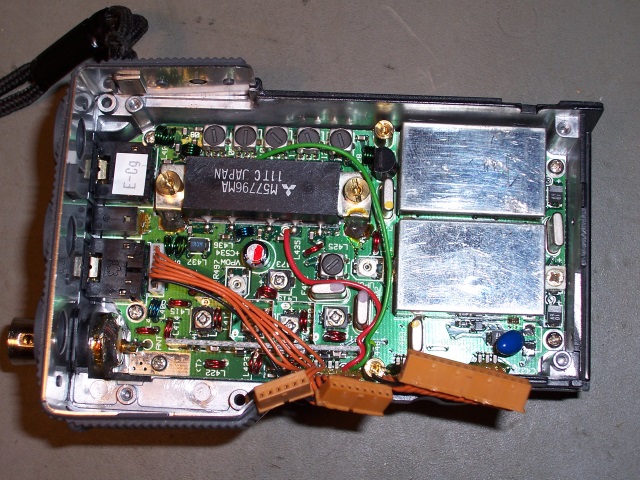
The re-assembly is simply the reverse of the dissassembly process. Make sure that the zinc oxide compound is replaced on the metal shield as shown above because it is used as a heatsink for components on the main board.
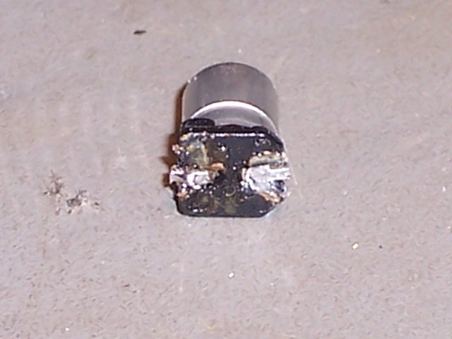
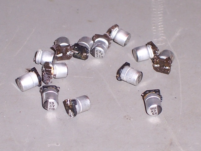
The photos above show a leaking capacitor and all of the faulty capacitors removed from the radio.
times since June 2008.
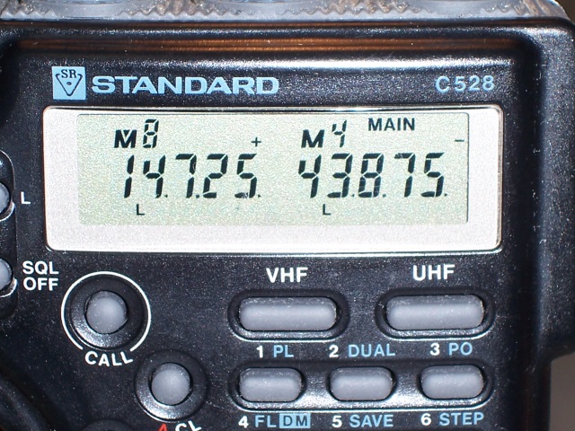
Standard C528 - Twin-Band 2m and 70cm
Handheld Transceiver Repair
Handheld Transceiver Repair

Search
