
Friday 22nd June, 2012 21:30
Ultrafire WF-1800L CREE LED Flashlight Repair
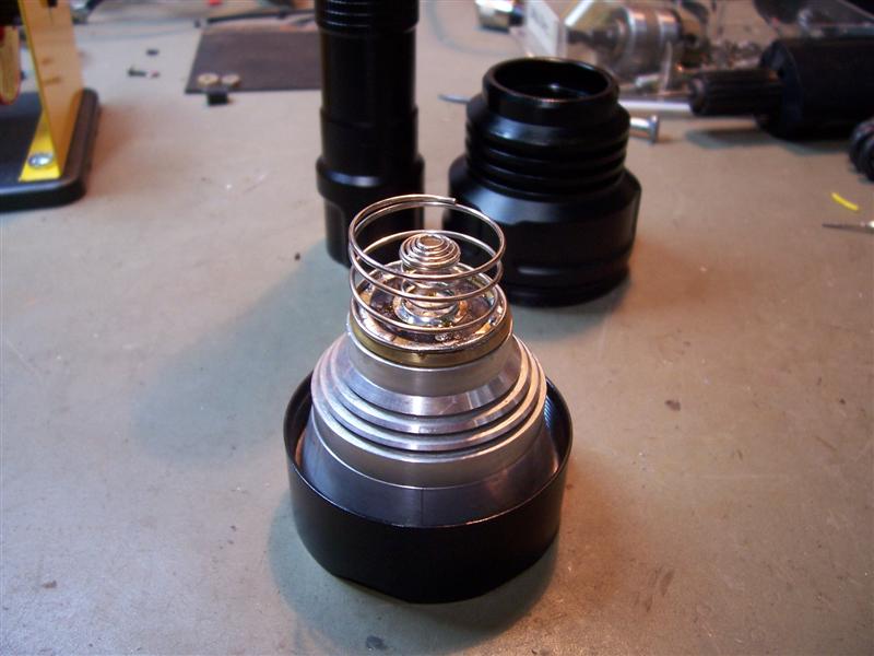
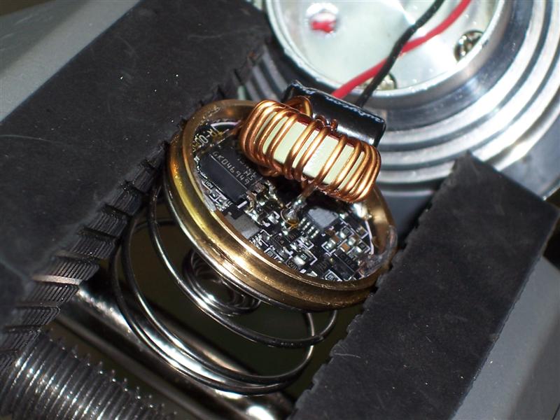
Once the diode, MOSFET and capacitor were returned to their respective positions, the inductor was soldered back into position also. A good rubber grip vice is essential to hold the unit steady whilst soldering.
Disassembly
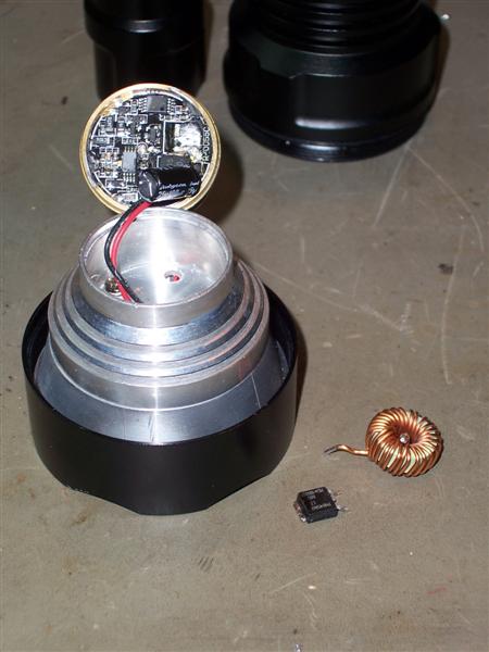
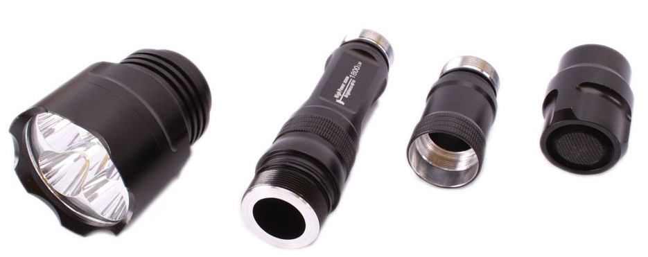
Disassembly of the flashlight was quite simple. It unscrews into components and the electronics are contained in the 'head' of the torch. To access the PCB containing the electronics, you simply need to pry away the bottom brass disc which is connected to the battery spring.
Disassembly of the flashlight was quite simple. It unscrews into components and the electronics are contained in the 'head' of the torch. To access the PCB containing the electronics, you simply need to pry away the bottom brass disc which is connected to the battery spring.
Background
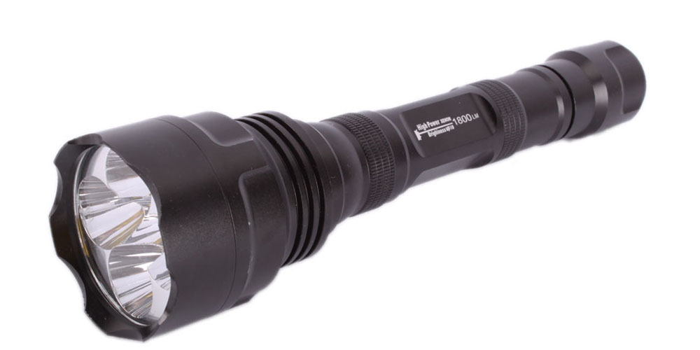
The "Ultrafire WF-1800L CREE® LED Flashlight (or Keygos KE-7) is a high power flashlight which uses 5 Cree Q5 L.E.D.'s to generate a bright light of supposedly around 1800 Lumens. In reality, the output quoted is theoretical, based upon the aggregate of the maximum output available at the surface of an individual chip as stated in the manufacturer's Data Sheet.
Practically, the total output is more like 900 Lumens at the lens face, which is still quite bright for a torch of this size.
Unfortunately, after about a year of providing good service, this flashlight died too, so I thought I'd pull it apart and see if it was repairable. I had been using it for over an hour continuously and I'm pretty sure that it overheated Considering the fact that it had failed suddenly, I wasn't expecting the repair to be too difficult.
Fault Discovered
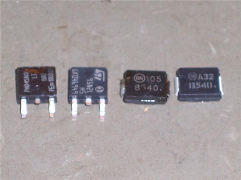
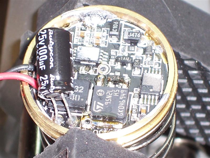
A quick multimeter check confirmed my suspicion that the switch mode driver FET (PHD45N03LTA) and a Shottky Diode (B540) had failed. The MOSFET was short circuited and the diode was open circuit. Element 14 (ex-Farnell) had the diodes in stock but I had to use an equivalent for the FET. Element 14 had a N Channel 25V 80A DPAK (STD95N2LH5) MOSFET at $1.60 each, so I thought I'd give that a try.
I removed both components with a conventional soldering iron and solderwick and cleaned the board of residual flux with Isopropanol.
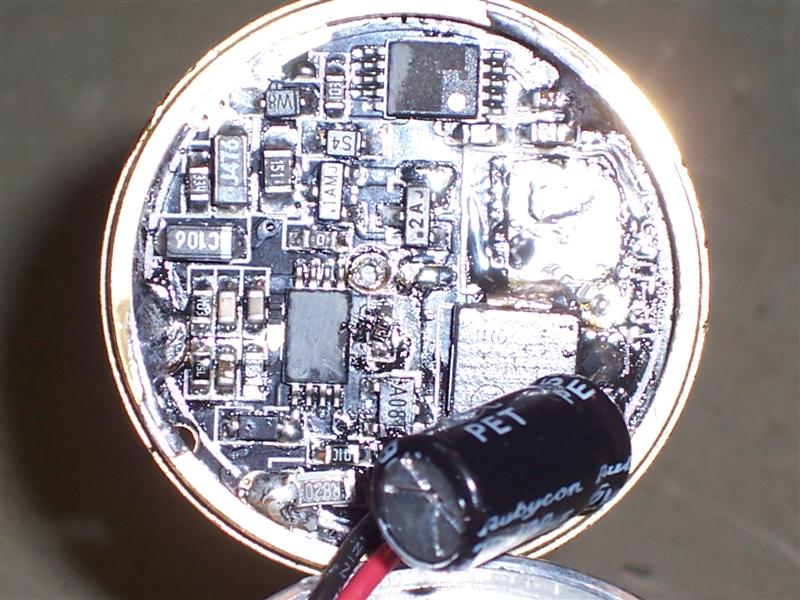
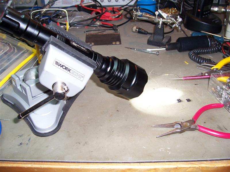
The flashlight was reassembled and worked perfectly upon testing. All modes functioned and an extended 'burn in' test did not cause the components to fail. As can be seen, the MOSFET does not really have adequate heatsinking and it really should be attached to the aluminium frame somehow. I couldn't see an easy way to do it so we'll see how it performs and if it fails again, I might have to look at providing a better heatsink for the MOSFET.
The total cost of components for this repair was AU$2.84.
The total cost of components for this repair was AU$2.84.
Disclaimer
This modification is offered as a all care, no responsibility mod. People wishing to repair their flashlight do so at their own risk.
This modification is not complex, however it does require a certain level of technical competence. If you are not experienced in repairing or servicing complex electronic equipment, then you will need to enlist the assistance of someone who is, in order to perform this upgrade.
The device uses extremely small surface mounted components, some of which will be prone to damage in high static fields. It is important to follow safe ESD practices and ensure that you are working in a fully static safe environment. It is also difficult to access some of the solder points and unless you are confident in your soldering ability, I would recommend that you do not attempt this on your own.
Whilst these modifications have been performed successfully without incident, I cannot be held responsible if you choose to go ahead with the modification and it does not work out for you, or you damage your unit further in the process. This information is provided as-is. If you choose to use this information, then the risk is entirely yours.
73s and regards
Ben
VK3KBC

Search
