
Background
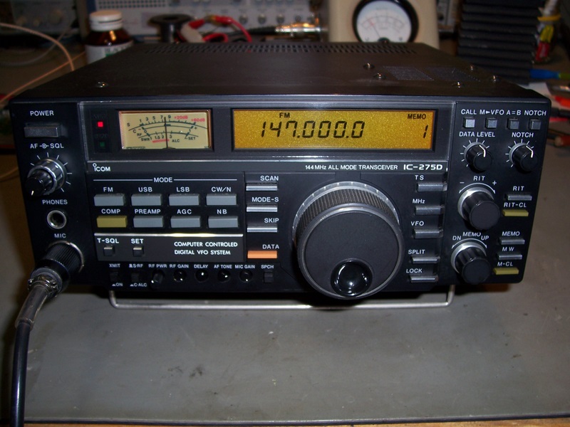
The IC-275D is a popular 2 metre, 100Watt All-Mode VHF Transceiver specifically made by ICOM for the Japanese (JA) market.
The 'D' Version is not too prevalent outside of Japan and due to the stricter radio communications regulations there, the 'D' version was 'locked down' more rigorously than the other versions intended for the US, EU, SW and VK markets.
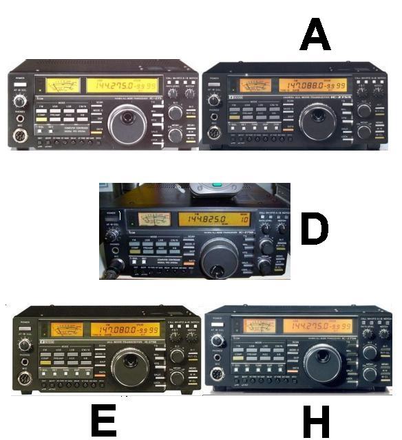
The units commonly found outside of JA are the IC-275 (25W 144-146Mhz), IC-275A (25 W 144-148Mhz), the IC-275E (25W 144-146Mhz) and the IC-275H(EU) (100W 144-146Mhz), IC-275H(US) (100W 144-148Mhz). All up, I believe that there are nine different versions in total that cover the US, EU, VK, SW and JA markets.
The IC-275D is a popular 2 metre, 100Watt All-Mode VHF Transceiver specifically made by ICOM for the Japanese (JA) market.
The 'D' Version is not too prevalent outside of Japan and due to the stricter radio communications regulations there, the 'D' version was 'locked down' more rigorously than the other versions intended for the US, EU, SW and VK markets.
The units commonly found outside of JA are the IC-275 (25W 144-146Mhz), IC-275A (25 W 144-148Mhz), the IC-275E (25W 144-146Mhz) and the IC-275H(EU) (100W 144-146Mhz), IC-275H(US) (100W 144-148Mhz). All up, I believe that there are nine different versions in total that cover the US, EU, VK, SW and JA markets.
There are numerous modifications published on the Web for the mainstream models which will allow the units to operate wideband mode, as well as to reactivate features that had been disabled for a particular geography. Unfortunately, the wideband transmit modifications that simply rely on a diode matrix reconfiguration do not work on the 'D' model and worse still, there is no way to open the TX to cover the full 144 - 148 Mhz band.
Since I had recently acquired a used IC-275D and wanted to use it in VK, I was keen to try to make it suitable for use in this region. To limit its use to simply 2m SSB work seemed like a waste, particularly considering it has 99 Memories which could be allocated to the large number of 2m repeaters within range of my QTH.
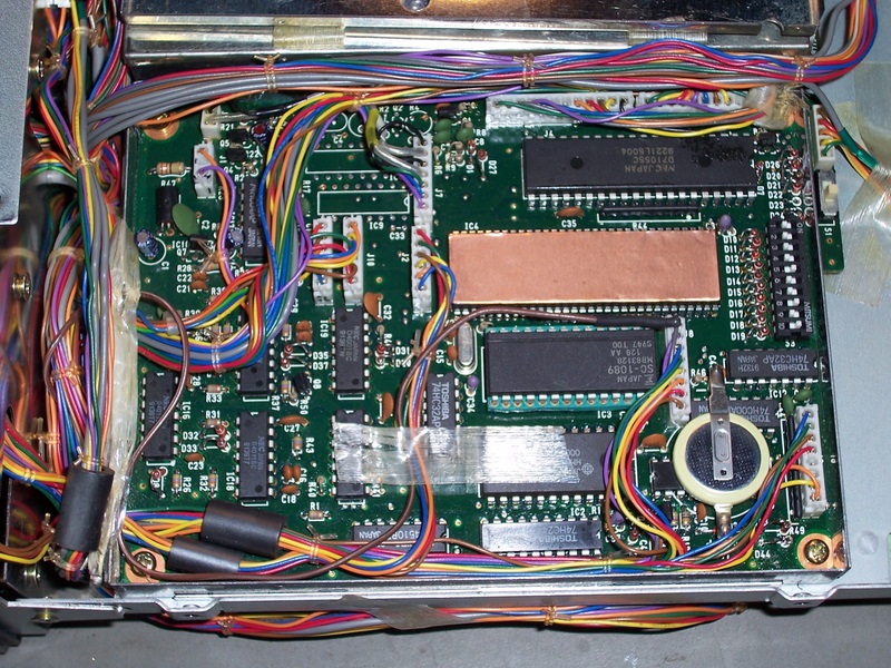
An analysis of the Logic Board revealed that the inhibiting feature was due to the code in ROM (IC3). The Logic board Microprocessor (Z80 compatible) resets both the TX and RX frequency to 145.000 Mhz if any attempt is made to transmit outside of the range of 144 - 145.995 Mhz.
Since I had recently acquired a used IC-275D and wanted to use it in VK, I was keen to try to make it suitable for use in this region. To limit its use to simply 2m SSB work seemed like a waste, particularly considering it has 99 Memories which could be allocated to the large number of 2m repeaters within range of my QTH.
An analysis of the Logic Board revealed that the inhibiting feature was due to the code in ROM (IC3). The Logic board Microprocessor (Z80 compatible) resets both the TX and RX frequency to 145.000 Mhz if any attempt is made to transmit outside of the range of 144 - 145.995 Mhz.
Modification
The modification to convert the IC-275D involves the following steps:
* Configuring the Diode Matrix to the IC-275H Model Configuration Setttings
* Desoldering IC3 on the Logic Board
* Inserting a good quality machined IC Socket in place of IC3
* Replacing IC3 with an IC-275H replacement ROM or EPROM with equivalent code
* Modifying the front key panel scan matrix to facilitate a 'Duplex' key
* Re-tuning the final amplifier for full coverage of 144 to 148 Mhz band
You will need the following:
* ICOM IC-275A/E/H Service Manual
* Fine tipped soldering station
* Thin solder
* Good quality desoldering station or solderwick and desoldering tool
* Good quality machined 28 Pin DIN IC socket
* Replacement ROM or EPROM (SC-1089) for IC3 on the Logic Board
* Some 1N4148 Diodes
* Some thin hookup wire
* Heatshrink to encase the 1N4148 and some of the hookup wire
* Electrical tape
* Sharp thin bladed hobby scalpel
* Small cable ties
Disclaimer
This modification is not complex, however it does require a certain level of technical competence. If you are not experienced in repairing or servicing complex radio equipment, then you will need to enlist the assistance of someone who is, in order to perform this upgrade.
Since the radio will be disassembled, it is important to follow safe ESD practices and ensure that you are working in a fully static safe environment. There are CMOS semiconductors in the Logic board and on other boards in close proximity, so they will be prone to damage in high static fields.
Whilst I have performed these modifications successfully without incident, I cannot be held responsible if you choose to go ahead with the modification and it does not work out for you, or you damage your radio in the process. This information is provided as-is. If you choose to use this information, then the risk is entirely yours.
Conversion
Remove IC3 from the Logic Board
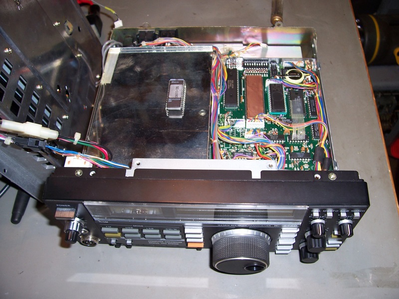
Consult the Service Manual to locate and access the Logic board and remove all connectors from it. Remove the board from the shielded enclosure and remove the bottom shield cover. Desolder the ROM (IC3) and insert the 28 Pin DIN Socket in its place.
Remove IC3 from the Logic Board
Consult the Service Manual to locate and access the Logic board and remove all connectors from it. Remove the board from the shielded enclosure and remove the bottom shield cover. Desolder the ROM (IC3) and insert the 28 Pin DIN Socket in its place.
Install the replacement ROM
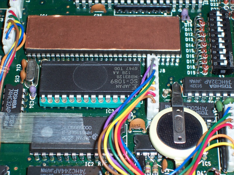
The original ROM in the IC-275D is a 27C256 EPROM marked SC-1193 . The ROM in the IC-275H is labelled "SC-1079" and is listed as ICOM Spare Part "1130003440 MBM27C128-25CZ-G/SC1079", however there were none in stock and I ordered an equivalent 1130003450 MB83128P-G-128 instead. This part was labelled F Japan SC-1089 - MB83128 128 AA 8947 T00. It worked perfectly.
The original ROM in the IC-275D is a 27C256 EPROM marked SC-1193 . The ROM in the IC-275H is labelled "SC-1079" and is listed as ICOM Spare Part "1130003440 MBM27C128-25CZ-G/SC1079", however there were none in stock and I ordered an equivalent 1130003450 MB83128P-G-128 instead. This part was labelled F Japan SC-1089 - MB83128 128 AA 8947 T00. It worked perfectly.
Configure the Diode Matrix to match the IC-275H Settings
Restore the Diode Matrix configuration so that D20, D22, D25 and D44 are installed as per Page 120 of the Service Manual. If wideband coverage is required, consult the existing articles on the Web (www.mods.dk) for those modifications, however removing D44 and D27 and installing D43 should be all that is required.
Re-attach the Logic board to the main chassis and reconnect all connectors. Replace the bottom shield but leave the top shield cover off for now.
Modify the operation of the Front Keypad to restore 'Duplex Key' functionality
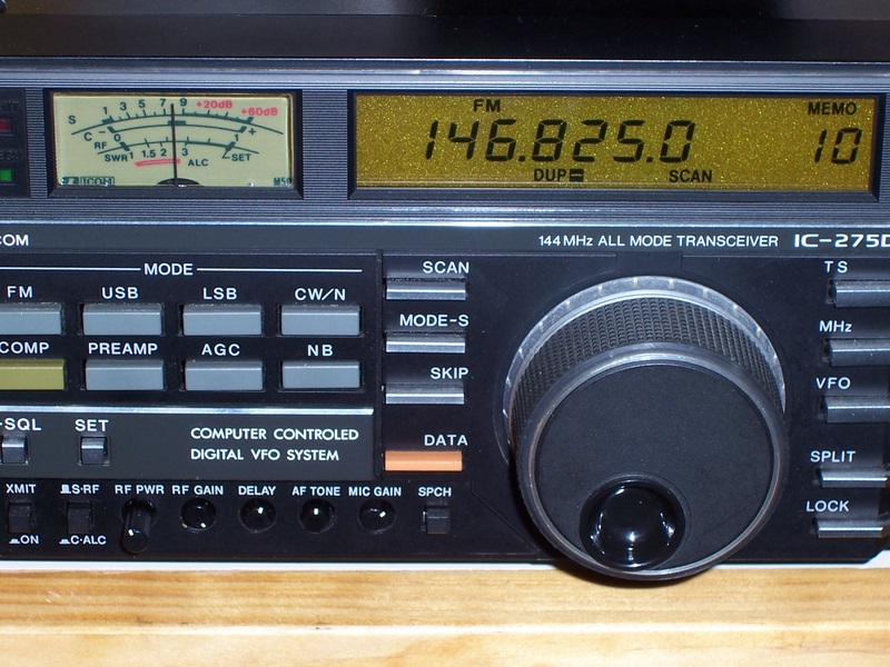
When comparing the IC-275D to the H model, you'll note that there are differences between the front panel keypads. In particular, there is no 'Duplex' button on the 'D' model, so it is not possible even after the ROM upgrade, to enter repeater offsets. You could use the 'split' function to work repeaters by utilising both VFO's, but the split is not stored in memory, so there is little benefit and you don't make effective use of the memories.
After examining the key scan matrix (Page 23 of Service Manual) and looking at which keys could be reassigned, I found that the 'Speech Synthesiser' button has a scan matrix of Y5, DB6 whereas the 'Duplex' button is Y5, DB0. Fortunately, the speech synthesiser button is one of the only buttons readily accessible from the rear of the control panel PCB.
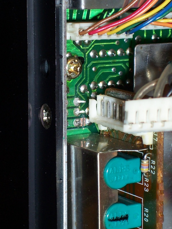
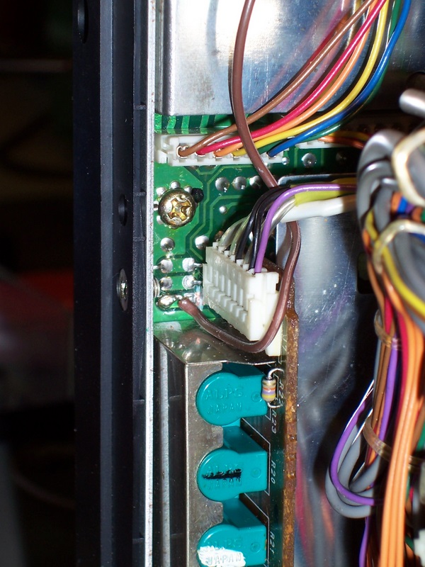
The modification to the keypad involves making a small cut to a PCB track to isolate the DB6 line and adding a wire and diode to connect the switch pad to the DB0 line on the Logic Board.
The PCB is cut as shown in the following picture and a wire is soldered onto the switch pad. The wire is routed up to and into the Logic board shielded enclosure.
When comparing the IC-275D to the H model, you'll note that there are differences between the front panel keypads. In particular, there is no 'Duplex' button on the 'D' model, so it is not possible even after the ROM upgrade, to enter repeater offsets. You could use the 'split' function to work repeaters by utilising both VFO's, but the split is not stored in memory, so there is little benefit and you don't make effective use of the memories.
After examining the key scan matrix (Page 23 of Service Manual) and looking at which keys could be reassigned, I found that the 'Speech Synthesiser' button has a scan matrix of Y5, DB6 whereas the 'Duplex' button is Y5, DB0. Fortunately, the speech synthesiser button is one of the only buttons readily accessible from the rear of the control panel PCB.
The modification to the keypad involves making a small cut to a PCB track to isolate the DB6 line and adding a wire and diode to connect the switch pad to the DB0 line on the Logic Board.
The PCB is cut as shown in the following picture and a wire is soldered onto the switch pad. The wire is routed up to and into the Logic board shielded enclosure.
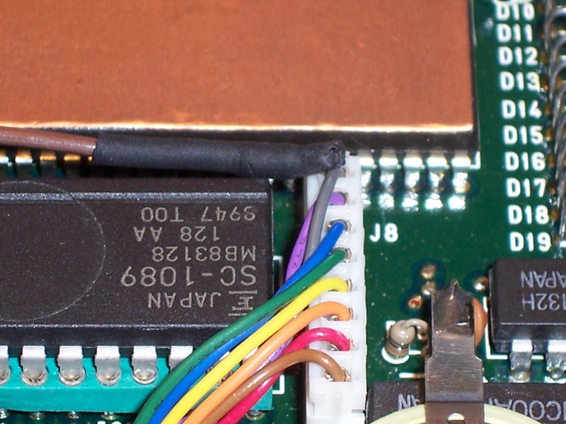
Leaving enough wire length to neatly place the wire along the edge of the inside of the Logic Board shield, trim the wire at a point adjacent to J8 and closest to IC4. (Refer to Page 66 of Service Manual)
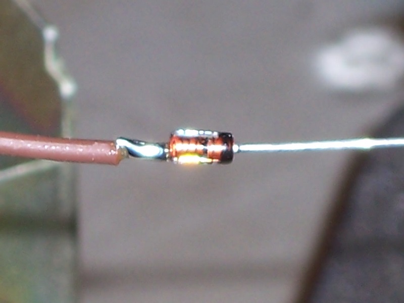
Solder the wire to the anode of a 1N4148 Diode.
Solder the wire to the anode of a 1N4148 Diode.
Cut a 20mm length of heatshrink tubing and slip it over the diode and wire.
Cut the excess lead off the Cathode of the diode leaving approximately 15mm left. Bend approximately 10mm at right angles and push the heatshrink along to the bend. All of the diode and the solder joint should be covered in heatshrink. Apply heat to the heatshrink and shrink to size.
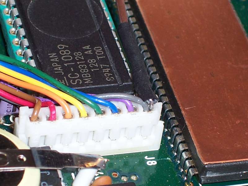
Using long nose pliers, force the 10mm length of wire vertically into the rear of the grey wire crimp connector at the end of J8 next to IC4. The wire should seat tightly and firmly into the crimp connector that is crimped onto the grey wire, negating the need to solder it to the connector.
Cut the excess lead off the Cathode of the diode leaving approximately 15mm left. Bend approximately 10mm at right angles and push the heatshrink along to the bend. All of the diode and the solder joint should be covered in heatshrink. Apply heat to the heatshrink and shrink to size.
Using long nose pliers, force the 10mm length of wire vertically into the rear of the grey wire crimp connector at the end of J8 next to IC4. The wire should seat tightly and firmly into the crimp connector that is crimped onto the grey wire, negating the need to solder it to the connector.
There should be no exposed diode lead visible. Just as a precaution, place a small piece of electrical tape over the connection and heatshrink to prevent the shield lid from contacting the diode lead should it move.
Secure the wire inside the Logic board enclosure and cable tie it outside of the enclosure to adjacent cable looms.
Secure the wire inside the Logic board enclosure and cable tie it outside of the enclosure to adjacent cable looms.
Completion
After the modifications above have been completed, power on the radio and you should note that the radio will now transmit over the entire 2m Amateur Band.
Pressing the Speech Synthesiser button will toggle the Duplex functions. I have not tried to enable the Reverse button as there were no spare buttons that could be easily reallocated. If I want to check a repeater input, I can simply use a VFO instead.
If required, re-tune the PA stage to broaden the RF output over the entire 2m Band. You may find that the radio was previously peaked for the lower part of the band. Refer to the Service Manual for the procedure.
The whole modification cost me approximately AU$50 in parts; a worthwhile investment for a useful upgrade to a great radio.
Saturday, 21 June 2008 13:58
ICOM IC-275D to IC-275H Conversion

Search
