
Bandsplit Problem
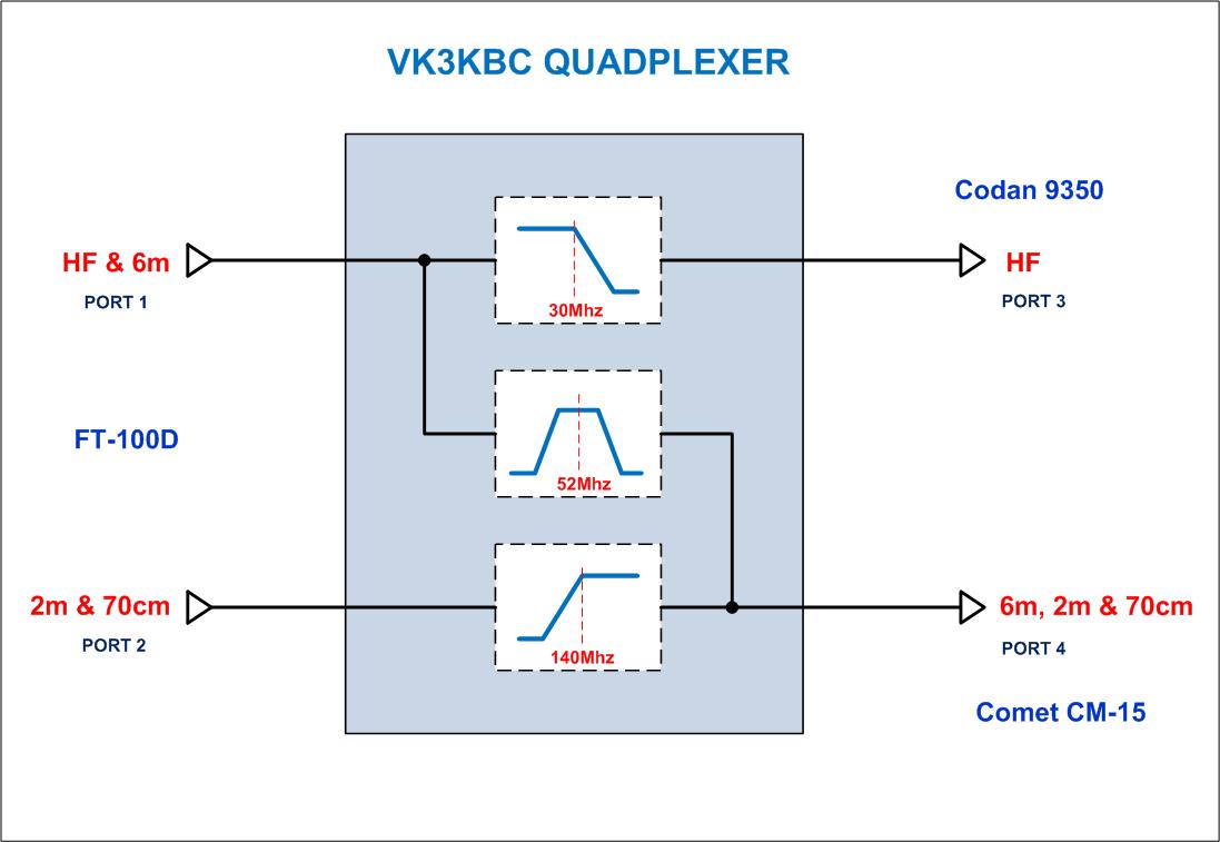
The problem with interfacing these antennas to the FT100D is that the radio has two RF outputs which don't align with the coverage provided by these antennas. The first RF port covers HF to 6m and the second covers 2m and 70cm.
This means that the 6m band RF output needs to be 'shifted' from the HF RF Port to the VHF / UHF RF port.
This can be achieved a number of ways such as using coaxial relays or by manually switching coax with antenna switches. I chose to use a diplexer approach due to the fact that there are no moving parts, DC power requirements or manual interventions required when changing bands.
The issue with using a diplexer approach is that you really need two diplexers in this case; one to seperate 6m from the HF port and another to combine it into the VHF/UHF port. Essentially what we need is a 'quadplexer'
Sunday, 21 June 2009 12:06
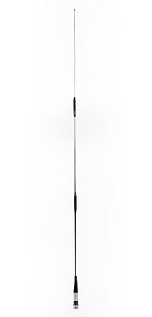
Comet SB-15 Antenna
2.15/4.5/7.2dBi (6m/2m/70Cms)
2.15/4.5/7.2dBi (6m/2m/70Cms)
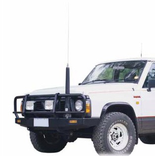
Codan 9350 Autotune Antenna
1.8 to 30 Mhz
1.8 to 30 Mhz
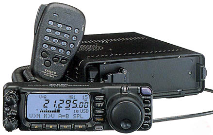
Yaesu FT100D
HF, 6m, 2m & 70cm
HF, 6m, 2m & 70cm
Quadplexer Design
After searching the Internet for suitable designs, I was dissapointed that there wasn't anything out there. I started to look for diplexer design material and found bits and pieces, but nothing detailed enough to assist.
There were free filter design programs available however each were limited to the number of nodes that they would work with, or they lacked features such as being able to adjust the input and output impedances or optimise filter leg characteristics.
I also quickly realised that there wasn't much technical documentation freely available which described the process by which someone could design complex filter systems.
Background
I have a Yaesu FT-100D which I want to interface with two antennas; an autotune antenna covering all of HF and another to cover 6m, 2m and 70cm.
Although the Yaesu ATAS-120 Antenna has been designed for use the FT-100D and will cover this entire frequency range, I want a more efficient, durable and rugged antenna system that will allow me to use the equipment in my 4x4 vehicle in rough terrain.
The antennas I have selected are a Codan 9350 Autotune whip and a Comet SB-15 6m, 2m and 70cm stainless steel antenna, which has some gain on each band. I plan to mount the tribander on a roof rack mount in the middle of the roof and the Codan antenna will be able to be mounted either on the front bullbar of the vehicle, or at the rear of the vehicle on a specially designed mount.
The optimal location for the Codan 9350 antenna is on the front of the vehicle, however new regulations in Victoria prevent the use of antennas greater than 30mm in width being mounted on the front of the car.
This forces me to have a rear antenna mounting point for use within Victoria and the bullbar mount for use elsewhere in Australia. (Another great example of bureaucrat imposed regulations that don't make sense).
I have found some excellent software for designing filters at http://www.aade.com/filter.htm and http://tonnesoftware.com, amongst others.
These software packages allowed me to begin experimenting with a theoretical design for the Quadplexer.
I found that 'Elsie' from Tonne Software allowed me to experiment with the component stages easily and quickly and plot the theoretical performance characteristics.
These software packages allowed me to begin experimenting with a theoretical design for the Quadplexer.
I found that 'Elsie' from Tonne Software allowed me to experiment with the component stages easily and quickly and plot the theoretical performance characteristics.


TO BE CONTINUED...
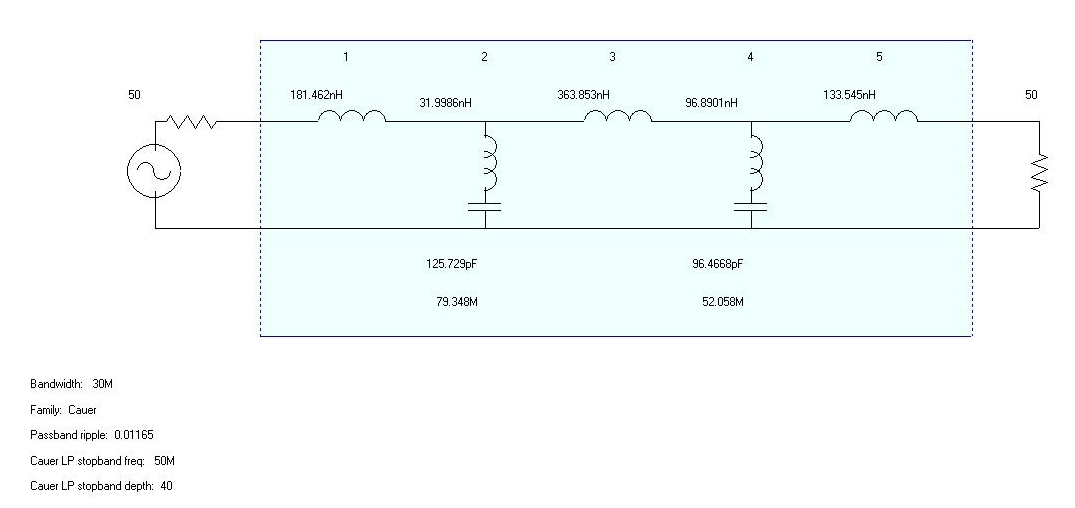
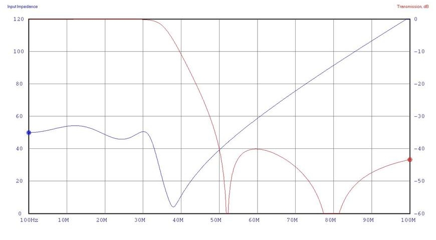
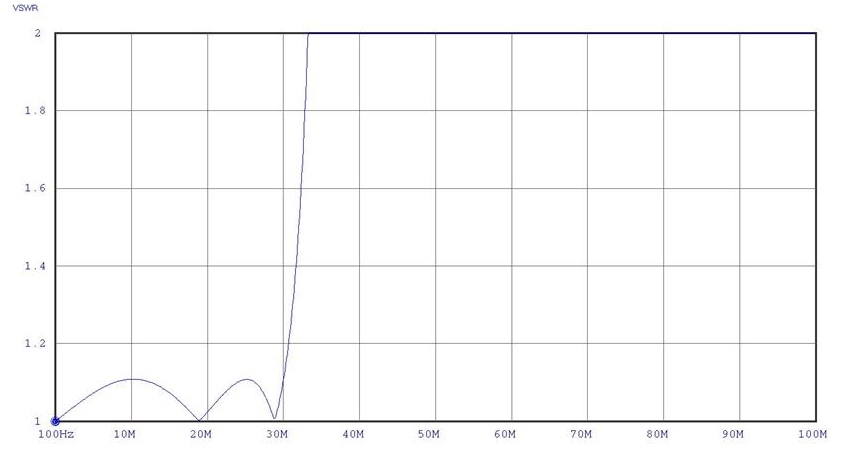
Low Pass Filter Stage
My design criteria are pretty basic. I want a mimimum component count, more inductors than capacitors (it's easier to adjust inductors) and a minimum of 40dB attenuation at the stop frequency of 30Mhz.
I first started with a Butterworth and Chebyshev filter design, however I found in both cases that the input impedance was not very linear over the required bandwidth. I then tried the Cauer (Elliptical) filter and was surprised to find that it provided a reasonable transfer characteristic along with a good input impedance across the HF band.
High Pass Filter Stage
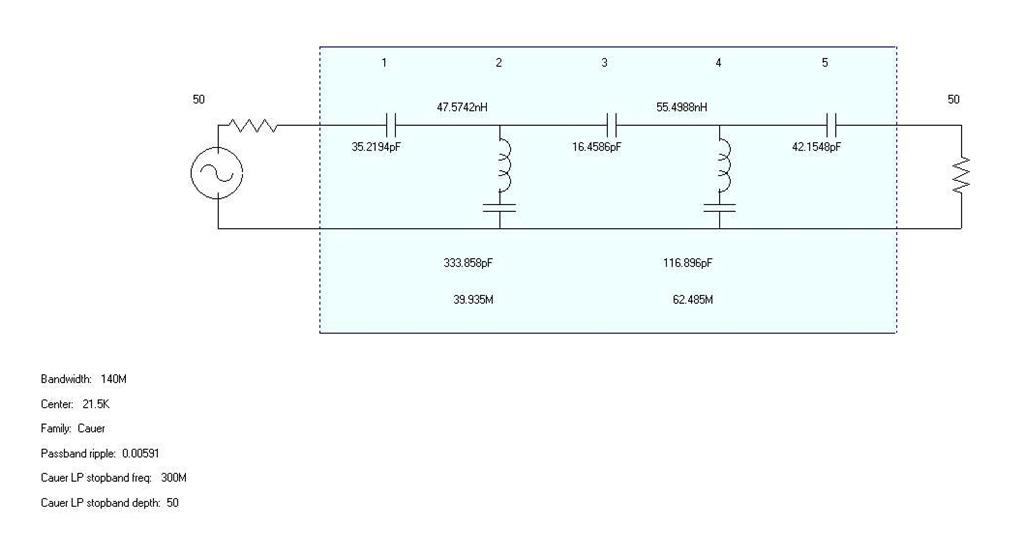
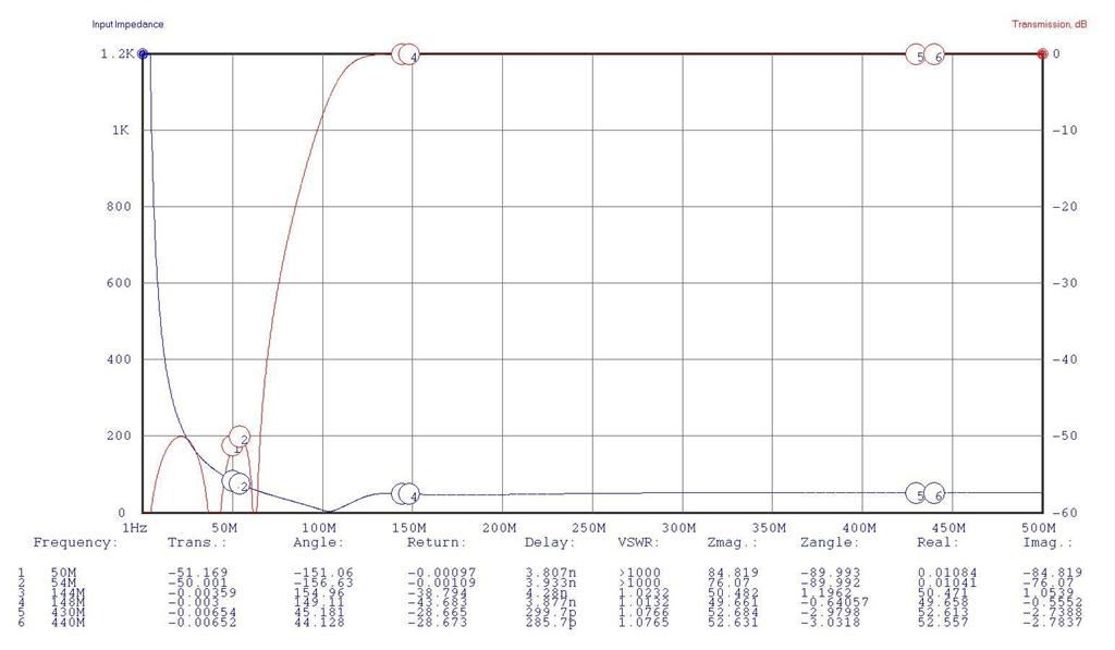
In the case of the High Pass Filter, I wanted 50db of attenuation at the stop frequency of 140 Mhz. Again I used a Cauer (Elliptical) filter design due to the excellent input impedance linearity and flat passband response.
In the case of the High Pass Filter, I wanted 50db of attenuation at the stop frequency of 140 Mhz. Again I used a Cauer (Elliptical) filter design due to the excellent input impedance linearity and flat passband response.
Band Pass Filter Stage
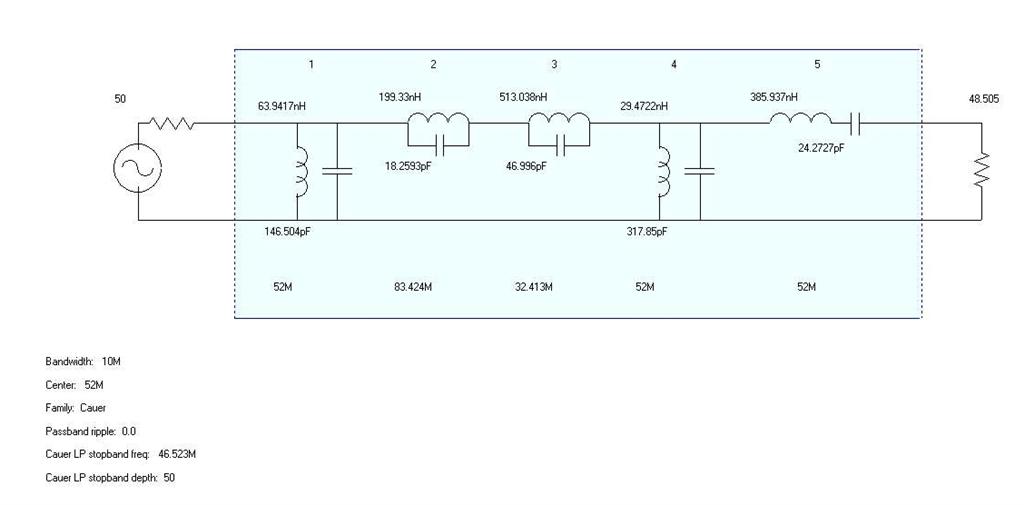
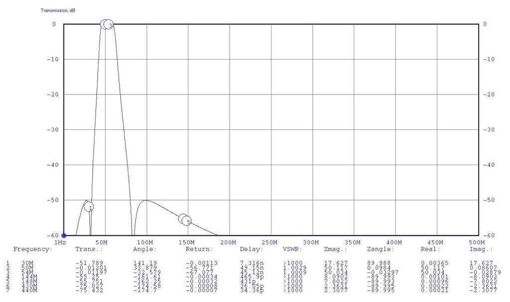
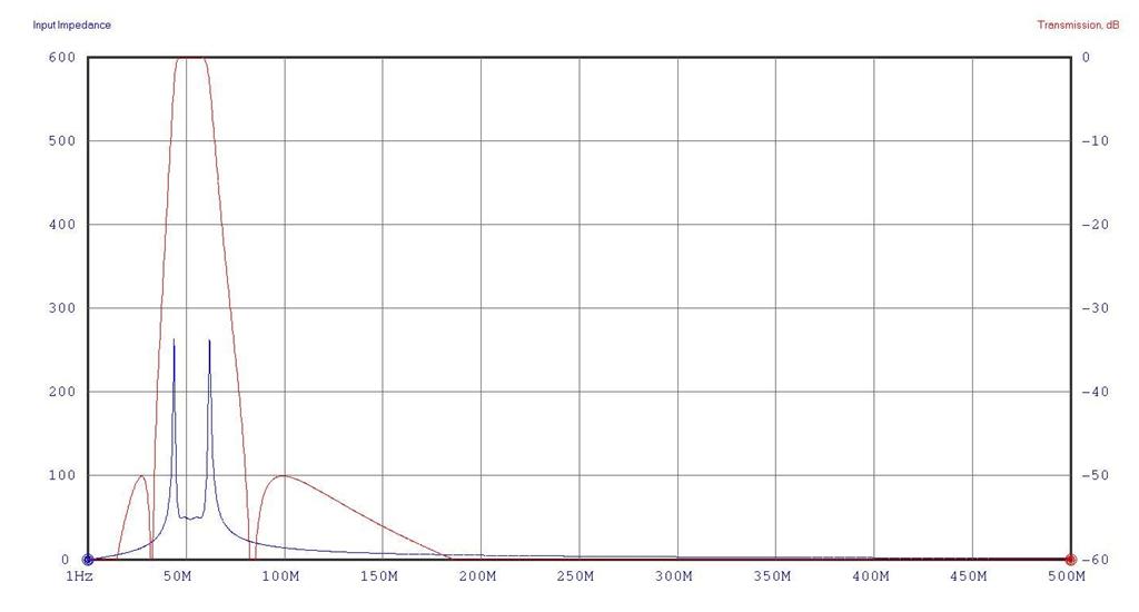
The Band Pass Filter needed to cover the 6m range of 50Mhz to 54Mhz with at least 50db of attenuation outside of that range.
Again I found the Cauer (Elliptical) filter design to be superior to the others due to the excellent input impedance linearity and flat passband response.
The Band Pass Filter needed to cover the 6m range of 50Mhz to 54Mhz with at least 50db of attenuation outside of that range.
Again I found the Cauer (Elliptical) filter design to be superior to the others due to the excellent input impedance linearity and flat passband response.
The Combined Theoretical Quadplexer Design
With all component filters combined, I should have a filter that'll provide the required response. Since each component filter operates at a different cutover frequency, there should be no interaction between them even when the LPF and HPF inputs and outputs are respectively paralleled with the BPF stage.
Isolation between each port should theoretically be around 90dB at the HF, 6m, 2m and 70cm operating frequencies and since only one component filter stage actually operates at any one time, the passband attenuation is always excellent.
Having completed the theoretical design, I realised that had I chosen simpler LPF, HPF, and BPF designs with say three stages per design and 25dB attenuation at the stop bands, I could have significantly reduced component count and still had a manageable 50dB of isolation between ports at the desired frequencies.
I did actually think of that earlier, but trying to model filters with minimal component stages did not produce encouraging performance graphs and I gave the idea away. In hindsight, had I manually combined the filters and used AADE's filter program to plot the response, it probably would have worked out fine, albeit with greater interaction over a larger bandwidth between ports.
That'll be version 2 :-)
Quadplexer Construction
To be continued ....
To be continued ....
Quadplexer for interfacing an FT-100D
with Codan and Comet Antennas
with Codan and Comet Antennas

Search
