
Monday 18th June, 2012 23:10
Nite Ize® LED Upgrade IQ Switch® Repair
Unfortunately, when the inductor wire breaks close to the former, there is no option but to try microsurgery to repair it, and this involves breaking away some of the glued ferrite ring surrounding the former.
Disclaimer
This modification is offered as a all care, no responsibility mod. People wishing to repair their IQ Switch do so at their own risk.
This modification is not complex, however it does require a certain level of technical competence. If you are not experienced in repairing or servicing complex electronic equipment, then you will need to enlist the assistance of someone who is, in order to perform this upgrade.
The device uses extremely small surface mounted components, some of which will be prone to damage in high static fields. It is important to follow safe ESD practices and ensure that you are working in a fully static safe environment. It is also difficult to access some of the solder points and unless you are confident in your soldering ability, I would recommend that you do not attempt this on your own.
Whilst these modifications have been performed successfully without incident, I cannot be held responsible if you choose to go ahead with the modification and it does not work out for you, or you damage your unit further in the process. This information is provided as-is. If you choose to use this information, then the risk is entirely yours.
73s and regards
Ben
VK3KBC
Disassembly
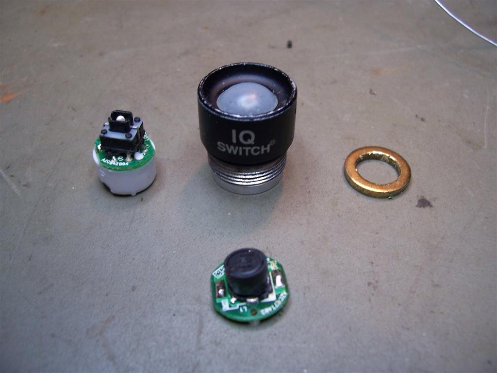
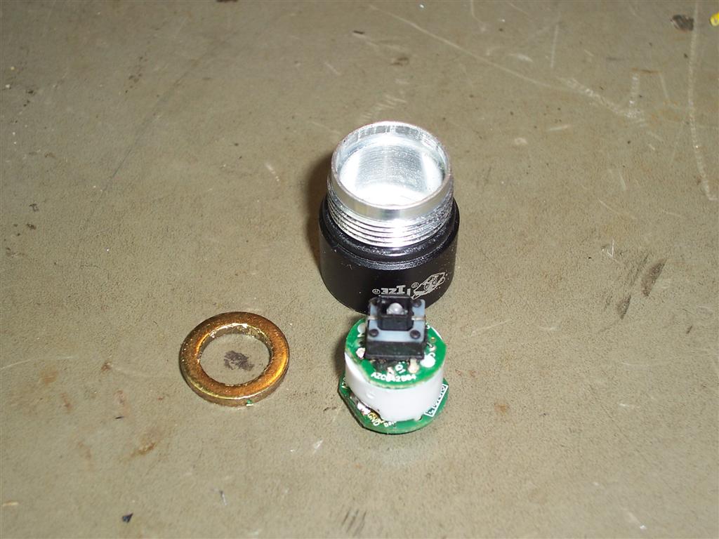
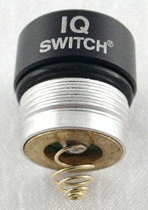
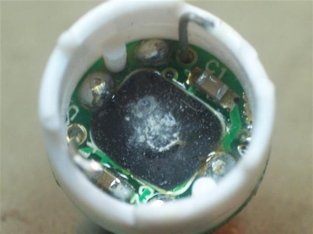
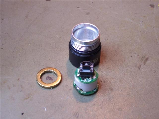
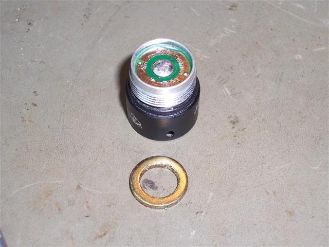
Disassembly of the IQ Switch was initially a bit tricky to work out. I wasn't sure if the unit was meant to be able to be pulled apart or whether components had been glued into place. As it turned out, all that needs to happen to pull the unit apart is to extract the brass ring that is wedged into place over the printed circuit board. Once that has been removed, the rest of the assembly can be extracted by pressing on the rubber boot covering the switch button. The whole assembly then pops out.
Disassembly of the IQ Switch was initially a bit tricky to work out. I wasn't sure if the unit was meant to be able to be pulled apart or whether components had been glued into place. As it turned out, all that needs to happen to pull the unit apart is to extract the brass ring that is wedged into place over the printed circuit board. Once that has been removed, the rest of the assembly can be extracted by pressing on the rubber boot covering the switch button. The whole assembly then pops out.
Background
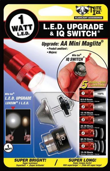
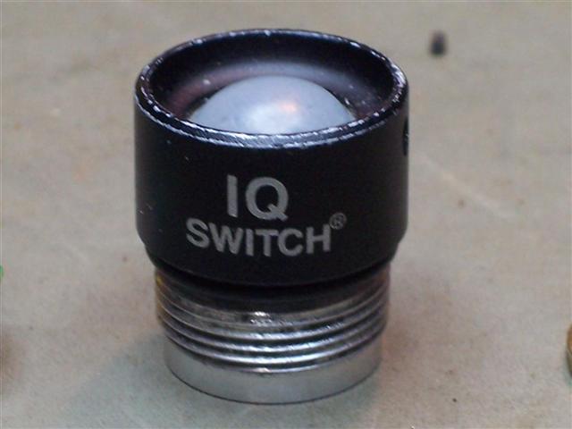
The "NITE IZE®" L.E.D. Upgrade & IQ Switch® is a great way of improving the performance of your trusty "Maglite®" torch. I've found that the IQ switch in particular, adds a very useful feature in being able to adjust the brightness of the Maglite® LED between low, medium and high output.
I've owned two of these upgrade kits for a number of years, however both IQ Switches had suddenly stopped operating inexplicably.
When my second one failed a few weeks ago after reliably operating on a daily basis for approximately two years, I decided it would be worthwhile investigating to see if I could find out why the unit had died.
You'll need a good quality, hardened fine tipped screwdriver. Wedge the tip between the base of the brass ring and the Printed Circuit Board and tap the screwdriver with a small hammer to move the ring up and away from the PCB. Rotate the unit and repeat in different spots around the board. Eventually, the ring will lift enough to allow it to be pried out.
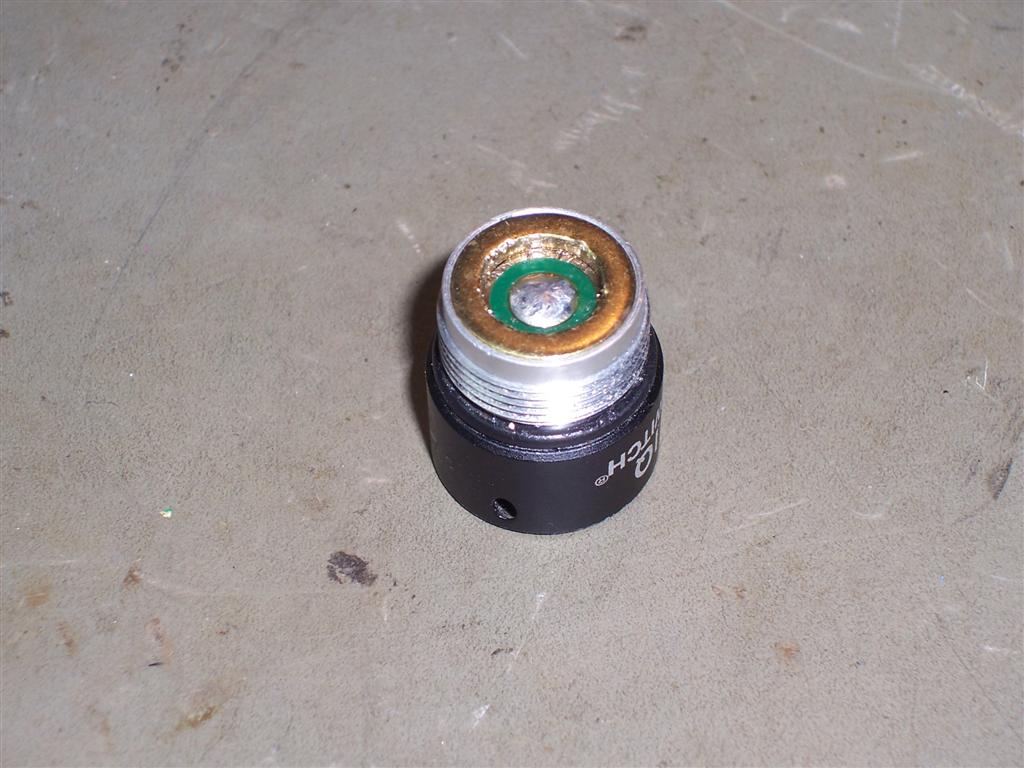
To re-install the brass ring later, just place it over the PCB and tap downward evenly around the ring and it will re-seat over the printed circuit board, making contact between the aluminium frame and the PCB conductor.
Common Fault Discovered
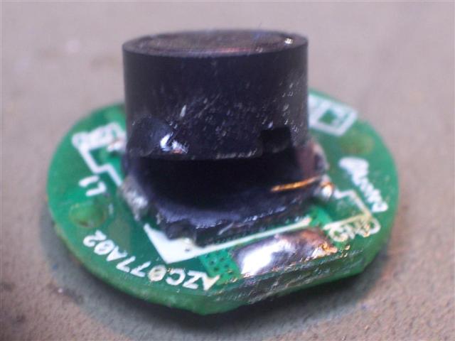
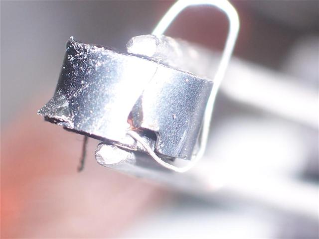
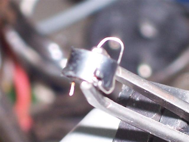
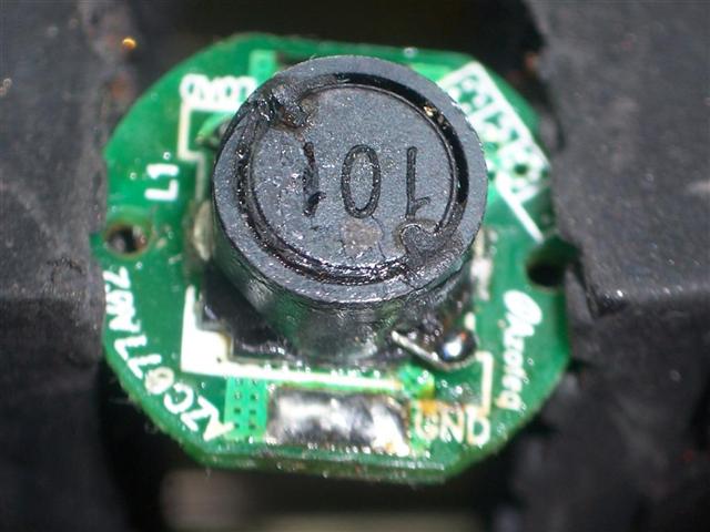
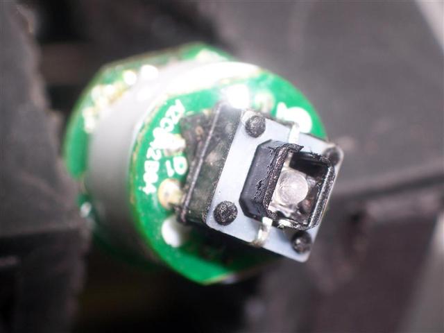
After disassembling both faulty IQ Switches, I noticed that in each case, the switching inductor had broken. I had expected to find a blown switching FET or similar, so I was surprised to see a mechanical fault. My guess is that this was probably due to the torch being dropped, on many occasions, onto a hard surface.
In both instances, the body of the ferrite former and coil assembly had separated from the ferrite base. When this had happened, the coil body was able to move around a bit like a pendulum and after a while, one of the inductor wires would fracture from the constant movement, causing an open circuit.
To re-install the brass ring later, just place it over the PCB and tap downward evenly around the ring and it will re-seat over the printed circuit board, making contact between the aluminium frame and the PCB conductor.
Common Fault Discovered
After disassembling both faulty IQ Switches, I noticed that in each case, the switching inductor had broken. I had expected to find a blown switching FET or similar, so I was surprised to see a mechanical fault. My guess is that this was probably due to the torch being dropped, on many occasions, onto a hard surface.
In both instances, the body of the ferrite former and coil assembly had separated from the ferrite base. When this had happened, the coil body was able to move around a bit like a pendulum and after a while, one of the inductor wires would fracture from the constant movement, causing an open circuit.
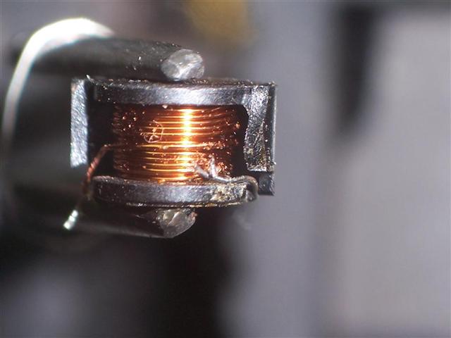
To repair the broken wire, remove some insulation from the broken end and thread some tinned wire of the same guage under it. Then solder the two. Once the junction is connected, cover with super glue (yes, you only get one shot at it) and then reseal by attaching the previously removed piece of ferrite ring.
When the glue is dry, apply more super glue to the base and re-attach the coil assembly to the base, which is still attached to the PCB. Then resolder the coil to the PCB.
When the glue is dry, apply more super glue to the base and re-attach the coil assembly to the base, which is still attached to the PCB. Then resolder the coil to the PCB.
Reattach the base PCB to the rest of the assembly and solder the two connecting wires.
It may be worth putting some neutral cure silicon or RTV Rubber around the inductor to prevent any movement in future. I didn't bother for now.
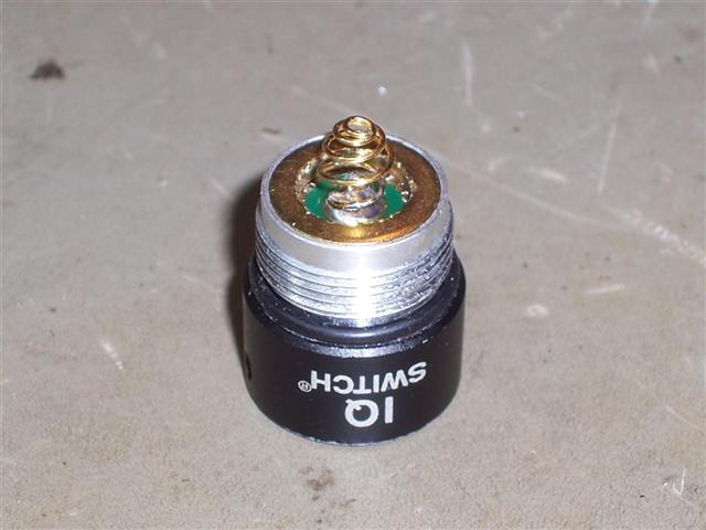
Press the brass ring back into position and resolder the beryllium copper spring back onto the centre pad of the PCB.
Both of my units worked perfectly after this repair.
Both of my units worked perfectly after this repair.

Search
